Search On This Site

Showing posts with label Manufacturing Process. Show all posts

Monday, 31 August 2015

Press Working Operations And Terminology

Press working may be defined as, a manufacturing process by which various components are made from sheet metal. This process is also termed as cold stamping. The machine used for press working is called a press.

The main features of a press are:

  •  A frame which support a ram or a slide and a bed, a source of mechanism for operating the ram in line with and normal to the bed.
  •  The ram is equipped with suitable punch/punches and a die block is attached to the bed.
  •  A stamping is produced by the downward stroke of the ram when the punch moves towards and into the die block.
  • The punch and die block assembly is generally termed as a “die set” or simple as the “die”
Press working operations:

The sheet metal operations done a press may be grouped into two categories.

1: Cutting operations

2: Forming operations

In cutting operations the work piece is stressed by its ultimate strength. The stresses caused in the metal the applied forces will be shear stresses. The cutting operations include:

(a) Blanking          (b) Punching        (c) Notching
(d) Perforating       (e) Trimming       (f) Shaving
(g) Slitting              (h) Lancing

In forming operations , the stresses are below the ultimate strength of the metal , in this operation , there is no cutting of the metal but only the contour of the work piece is changed to get the desired product.

The forming operations include:

(a) Bending              (b) Drawing       (c) Squeezing

A simple cutting die used for punching and blanking operation as shown:
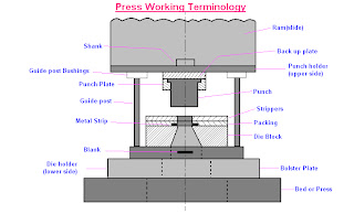
1: Bed:
The bed is the lower part of the press frame that serves as a table to which a
Bolster plate is mounted.

2: Bolster Plate:
This is a thick plate secured to the press bed , which is used for locating and
supporting the die assembly. It is usually 5 to 12.5 cm thick.

3: Die Set:
It is unit assembly which incorporates a lower and upper shoe, two or more guide parts and guide part bushings.

4: Die Block:
It is a block or a plate which contains a die cavity

5: Lower Shoe:
The lower shoe of the a die set is generally mounted on the bolster plate of a press. The die block is mounted on the lower shoe, also the guide post are mounted on it.

6: Punch :
This is male component of  a die assembly, which is directly or indirectly moved by and fastened to the press ram or slide.

7: Upper Shoe:
This is the upper part of the die set which contains guide post bushings.

8: Punch Plate :
The punch plate or punch retainer fits closely over the body of the punch and holds it in proper relative position.

9: Back up Plate:
Back up plate or pressure plate is placed so that intensity of pressure does
not become excessive on punch holder. The plate distributes the pressure
over a wide area and the intensity of pressure on the punch holder is reduced
to avoid crushing.

10: Stripper:
It is a plate which is used to strip the metal strip from cutting a non-cutting
Punch or die. It may also guide the sheet.

Saturday, 1 August 2015

Types Of Gear

Following are Types Of Gear:


  1. Spur Gear
  2. Helical Gear
  3. Herringbone Gear
  4. Bevel Gear
  5. Worm Gear
  6. Rack and Pinion
  7. Internal and External Gear
  8. Face Gear
  9. Sprockets

    1) Spur Gear-Parallel and co-planer shafts connected by gears are called spur gears. The arrangement is called spur gearing.


Spur gears have straight teeth and are parallel to the axis of the wheel. Spur gears are the most common type of gears. The advantages of spur gears are their simplicity in design, economy of manufacture and maintenance, and absence of end thrust. They impose only radial loads on the bearings.

Spur gears are known as slow speed gears. If noise is not a serious design problem, spur gears can be used at almost any speed.


      2)     Helical Gear-Helical gears have their teeth inclined to the axis of the shafts in the form of a helix, hence the name helical gears.


These gears are usually thought of as high speed gears. Helical gears can take higher loads than similarly sized spur gears. The motion of helical gears is smoother and quieter than the motion of spur gears.

Single helical gears impose both radial loads and thrust loads on their bearings and so require the use of thrust bearings. The angle of the helix on both the gear and the must be same in magnitude but opposite in direction, i.e., a right hand pinion meshes with a left hand gear.
    (3)   Herringbone Gear - Herringbone gears resemble two helical gears that have been placed side by side. They are often referred to as "double helicals". In the double helical gears arrangement, the thrusts are counter-balanced. In such double helical gears there is no thrust loading on the bearings.

   (4)  Bevel/Miter Gear-Intersecting but coplanar shafts connected by gears are called bevel gears. This arrangement is known as bevel gearing. Straight bevel gears can be used on shafts at any angle, but right angle is the most common. Bevel Gears have conical blanks. The teeth of straight bevel gears are tapered in both thickness and tooth height. 

Spiral Bevel gears: In these Spiral Bevel gears, the teeth are oblique. Spiral Bevel gears are quieter and can take up more load as compared to straight bevel gears.


    Zero Bevel gear: Zero Bevel gears are similar to straight bevel gears, but their teeth are curved lengthwise. These curved teeth of zero bevel gears are arranged in a manner that the effective spiral angle is zero.
   (5)  Worm Gear- Worm gears are used to transmit power at 90° and where high reductions are required. The axes of worm gears shafts cross in space. The shafts of worm gears lie in parallel planes and may be skewed at any angle between zero and a right angle.In worm gears, one gear has screw threads. Due to this, worm gears are quiet, vibration free and give a smooth output.Worm gears and worm gear shafts are almost invariably at right angles.
(6) Rack and Pinion- A rack is a toothed bar or rod that can be thought of as a sector gear with an infinitely large radius of curvature. Torque can be converted to linear force by meshing a rack with a pinion: the pinion turns; the rack moves in a straight line. Such a mechanism is used in automobiles to convert the rotation of the steering wheel into the left-to-right motion of the tie rod(s). Racks also feature in the theory of gear geometry, where, for instance, the tooth shape of an interchangeable set of gears may be specified for the rack (infinite radius), and the tooth shapes for gears of particular actual radii then derived from that. The rack and pinion gear type is employed in a rack railway.
(    ( 7)      Internal & External Gear- An external gear is one with the teeth formed on the outer surface of a cylinder or cone. Conversely, an internal gear is one with the teeth formed on the inner surface of a cylinder or cone. For bevel gears, an internal gear is one with the pitch angle exceeding 90 degrees. Internal gears do not cause direction reversal.

    (8)      Face Gears- Face gears transmit power at (usually) right angles in a circular motion. Face gears are not very common in industrial application.
(   (9)      Sprockets-Sprockets are used to run chains or belts. They are typically used in conveyor systems.

    Gears may also be classified according to the position of axis of shaft:
a.Parallel
  1.Spur Gear
  2.Helical Gear
  3.Rack and Pinion
b. Intersecting
  Bevel Gear
c. Non-intersecting and Non-parallel
  worm and worm gears


Thursday, 30 July 2015

Manufacturing Science : Types And Detail About DRILLING MACHINE


DRILLING MACHINE


Drilling is an operation of making a circular hole by removing a volume of metal from the job by cutting tool called drill. A drill is a rotary end-cutting tool with one or more cutting lips and usually one or more flutes for the passage of chips and the admission of cutting fluid. A drilling machine is a machine tool designed for drilling holes in metals. It is one of the most important and versatile machine tools in a workshop. Besides drilling round holes, many other operations can also be performed on the drilling machine such as counter- boring, countersinking, honing, reaming, lapping, sanding etc.

This machine consists of following parts

1. Base
2. Pillar
3. Main drive

4. Drill spindle
5. Feed handle

6. Work table

Tuesday, 28 July 2015

Manufacturing Process : Powder Metallurgy

What is Powder Metallurgy?

powder metallurgy

Powder metallurgy (PM) is a term covering a wide range of ways in which materials or components are made from metal powders. PM processes can avoid, or greatly reduce, the need to use metal removal processes, thereby drastically reducing yield losses in manufacture and often resulting in lower costs.

Powder metallurgy is used for manufacturing products or articles from powdered metals by placing these powders in molds and are compacting the same using heavy compressive force.

Thursday, 2 July 2015

Introduction To Lathe Machine

Lathe is one of the most versatile and widely used machine tools all over the world.The main function of a lathe is to remove metal from a job to give it the required shape and size. The job is securely and rigidly held in the chuck or in between centres on the lathe machine and then turn it against a single point cutting tool which will remove metal from the job in the form of chips.

An engine lathe is the most basic and simplest form of the lathe.Basic Operation such as drilling, reaming, boring, taper turning, knurling, screw thread cutting, grinding etc.. can be perform.

Sunday, 21 June 2015

Casting Process Introduction

Casting Definition:

Casting is a manufacturing process by which a liquid material is usually poured into a mold, which contains a hollow cavity of the desired shape, and then allowed to solidify. The solidified part is also known as a casting, which is ejected or broken out of the mold to complete the process.

There Are Different Types Of Casting Process:

1. PERMANENT MOLD OR GRAVITY DIE CASTING

This process is commonly known as permanent mold casting in U.S.A and gravity die casting in England.
A permanent mold casting makes use of a mold or metallic die which is permanent.
Molten metal is poured into the mold under gravity only and no external pressure is applied to force the liquid metal into the mold cavity. However, the liquid metal solidifies under pressure of metal in the risers, etc.

2. SLUSH CASTING

Image result for SLUSH CASTINGSlush casting is an extension of permanent mold casting or metallic mold casting.It is used widely for production of hollow casting without the use of core.The process is similar to metallic mold casting only with the difference that mold is allowed to open at an early stage and some un-solidified molten metal fall down leaving hollowness in the cast object.


3. PRESSURE DIE CASTING

Unlike permanent mold or gravity die casting, molten metal is forced into metallic mold or die under pressure in pressure die casting.The application of high pressure is associated with the high velocity with which the liquid metal is injected into the die to provide a unique capacity for the production of intricate components at a relatively low cost.

Die casting is widely used for mass production and is most suitable for non-ferrous metals and al1oys of low fusion temperature. The casting process is economic and rapid. The
surface achieved in casting is so smooth that it does not require any finishing operation.

4. Hot chamber die-casting

Hot chamber die-casting machine is the oldest of die-casting machines which is simplest to operate.

5. SHELL MOLD CASTING

Shell mold casting process is recent invention in casting techniques for mass production and smooth surface finish.It consists of making a mold that possesses two or more thin shells thermosetting resin bonded sands.

6. CENTRIFUGAL CASTING
Image result for CENTRIFUGAL CASTING
In centrifugal casting process, molten metal is poured into a revolving mold and allowed to solidify molten metal by pressure of centrifugal force.Due to centrifugal force, the castings produced will be of high density type and of good strength.

6. CONTINUOUS CASTING

In this process the molten metal is continuously poured in to a mold cavity around which a facility for quick cooling the molten metal to the point of solidification. The solidified metal is then continuously extracted from the mold at predetermined rate.


Related Posts Plugin for WordPress, Blogger...