Search On This Site

Showing posts with label Mechanical Theory. Show all posts

Thursday, 24 September 2015

NDT- Non Destructive Testing

Nondestructive testing - NDT - use test methods to examine an object, material or system without impairing its future usefulness. Non-destructive testing is often required to verify the quality of a product or a system. Commonly used techniques are

AET - Acoustic Emission Testing

Acoustic Emission Testing takes advantage of the sharp sound that PCCP emits when it breaks or slips to identify areas of active distress within a construction. AET can be used to verify the structural integrity of pressure vessels, spheres, high temperature reactors and piping, coke drums, above ground storage tanks, cryogenic storage tanks and more. The inspection is executed externally and shut-down of the process may often not be necessary.

ART - Acoustic Resonance Testing

After an impact a specimen will vibrate in certain characteristic modes and frequencies that can be measured by a microphone or laser vibrometer. Acoustic sonic and ultrasonic resonance analysis is a non-destructive testing technique that allows testing of a wide range of test objects. Typical detecting faults are cracks, cavities, detached layers, material inconsistencies, hardness deviation in materials.

Friday, 18 September 2015

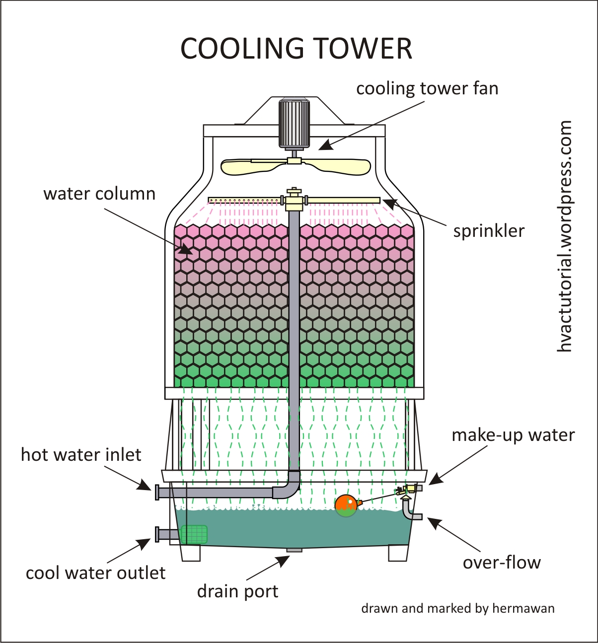
Cooling Tower


Cooling tower are very important part of many chemical plants. primary task of cooling tower is to reject heat into the atmosphere.


Cooling Tower Type:

Mainly there is two type : Natural draft and mechanical draft

Natural draft cooling tower are large in construction and mainly use for water flow rate more than 45000 m^3/hr.

There are three arrangement in mechanical draft:

1. Counter Flow induced draft
2.counter flow forced draft
3.cross flow induced draft

Main component of cooling tower:

Frame and casing, fill, cold water basin, drift eliminator, air inlet, louvers, nozzles and fan.

Wednesday, 2 September 2015

Basic Of Steam Turbine

The steam turbine is universally used as prime mover in steam power plants.

Flow over Blades:

The steam turbine obtains its motive power from the change of momentum of a jet of steam flowing over a curved blade. The steam jet, in moving over the curved surface of the blade, exerts a pressure on the blade owing to its centrifugal force. This centrifugal force is exerted normal to the blade surface as shown in figure and acts along the whole length of the blade.

The resultant of these centrifugal forces plus the effect of change of velocity is the motive force on the blade. It should be realized that the blade obtains no motive form any impact of the jet, because the blade is so designed that the steam jet will glide on and off the blade without any tendency to strike it. In principle, it is analogous to a train passing around a railway curve. The train exerts a radially outward force on the line due to the centrifugal force.

Moving and Fixed Blades

In a steam turbine, a number of small blades are fixed to the ring of a revolving wheel or rotor. Jets of steam of a high velocity are obtained by expansion through nozzles and are directed on to the blades. The effective force of these jets, acting on the blades, rotates the wheel.

In modern turbines several of the wheel of moving blades are keyed to the same shaft, having a ring of fixed blades between each wheel of moving blades. These fixed blades are fixed to the turbine casing. Their object is to receive the steam jet from the moving blade ring and to divert it on to the next ring of moving blades by changing its direction as shown. This diversion may continue over several rings of moving and fixed blades until the whole of the kinetic energy of the steam jet is expended.

Tuesday, 4 August 2015

Power Transmission System : Clutches,Torque Converters,Mechanical Transmission


Image result for clutches in mechanical engineeringGENERAL CONSIDERATIONS
The first decision in designing an engine installation is selection of the coupling and drive method to connect the engine to the driven equipment..
The coupling and drive selection connections are closely related to the proper selection of engine support and mounting. This ensures a successful trouble-free installat
ion from the standpoint of both the engine and driven equipment, as well as the power transmission components. (Refer to Mounting and Alignment section.)

A rigid precision-type mounting system must be provided for both the engine and driven equipment if a solid or nearly solid driveline is utilized.

Drive components which utilize universal joints, drive shafts or belts, and chain-type drives permit slightly greater alignment deviations.

When selecting the power transmission system, the possible need for a complete torsional analysis must be considered. System incompatibility will result in premature and/or avoidable failures.Refer to Mounting and Alignment section

CLUTCHES
General Description and Selection Considerations
Engine starting capability is normally limited and the direct connection of large mass
driven equipment makes starting difficult or impossible, therefore, a type of clutch or
disconnect device may not only be desirable but necessary.

Exceptions, if properly sized to the engine starting capability, may be centrifugal pumps, fans or propellers, and generators which provide a direct connected load with
a low starting torque requirement. Certain compressors which utilize a starting “unloading device” may also be direct connected.

Piston-type pumps, most compressors, belt- and chain-driven equipment, and all mobile vehicles will require an engine disconnect system.

The engine disconnect feature provides an important safety and service function. It permits rotating the engine for service and adjustment, as well as servicing the driven
equipment without disconnecting the drive-train. It also permits engine warm up before applying load — an accepted requirement for extended engine life. On multiple engine installations driving into a common compound or driven machine, it permits operating at less than full power level if desired, as well as at partial power should one engine be down for routine service or because of failure.

Numerous devices are available for connection or engagement of the engine to the driven machine. The device selection will depend on the desired engagement function; however, several general considerations must be made regardless of the
device selected.

Saturday, 1 August 2015

Types Of Gear

Following are Types Of Gear:


  1. Spur Gear
  2. Helical Gear
  3. Herringbone Gear
  4. Bevel Gear
  5. Worm Gear
  6. Rack and Pinion
  7. Internal and External Gear
  8. Face Gear
  9. Sprockets

    1) Spur Gear-Parallel and co-planer shafts connected by gears are called spur gears. The arrangement is called spur gearing.


Spur gears have straight teeth and are parallel to the axis of the wheel. Spur gears are the most common type of gears. The advantages of spur gears are their simplicity in design, economy of manufacture and maintenance, and absence of end thrust. They impose only radial loads on the bearings.

Spur gears are known as slow speed gears. If noise is not a serious design problem, spur gears can be used at almost any speed.


      2)     Helical Gear-Helical gears have their teeth inclined to the axis of the shafts in the form of a helix, hence the name helical gears.


These gears are usually thought of as high speed gears. Helical gears can take higher loads than similarly sized spur gears. The motion of helical gears is smoother and quieter than the motion of spur gears.

Single helical gears impose both radial loads and thrust loads on their bearings and so require the use of thrust bearings. The angle of the helix on both the gear and the must be same in magnitude but opposite in direction, i.e., a right hand pinion meshes with a left hand gear.
    (3)   Herringbone Gear - Herringbone gears resemble two helical gears that have been placed side by side. They are often referred to as "double helicals". In the double helical gears arrangement, the thrusts are counter-balanced. In such double helical gears there is no thrust loading on the bearings.

   (4)  Bevel/Miter Gear-Intersecting but coplanar shafts connected by gears are called bevel gears. This arrangement is known as bevel gearing. Straight bevel gears can be used on shafts at any angle, but right angle is the most common. Bevel Gears have conical blanks. The teeth of straight bevel gears are tapered in both thickness and tooth height. 

Spiral Bevel gears: In these Spiral Bevel gears, the teeth are oblique. Spiral Bevel gears are quieter and can take up more load as compared to straight bevel gears.


    Zero Bevel gear: Zero Bevel gears are similar to straight bevel gears, but their teeth are curved lengthwise. These curved teeth of zero bevel gears are arranged in a manner that the effective spiral angle is zero.
   (5)  Worm Gear- Worm gears are used to transmit power at 90° and where high reductions are required. The axes of worm gears shafts cross in space. The shafts of worm gears lie in parallel planes and may be skewed at any angle between zero and a right angle.In worm gears, one gear has screw threads. Due to this, worm gears are quiet, vibration free and give a smooth output.Worm gears and worm gear shafts are almost invariably at right angles.
(6) Rack and Pinion- A rack is a toothed bar or rod that can be thought of as a sector gear with an infinitely large radius of curvature. Torque can be converted to linear force by meshing a rack with a pinion: the pinion turns; the rack moves in a straight line. Such a mechanism is used in automobiles to convert the rotation of the steering wheel into the left-to-right motion of the tie rod(s). Racks also feature in the theory of gear geometry, where, for instance, the tooth shape of an interchangeable set of gears may be specified for the rack (infinite radius), and the tooth shapes for gears of particular actual radii then derived from that. The rack and pinion gear type is employed in a rack railway.
(    ( 7)      Internal & External Gear- An external gear is one with the teeth formed on the outer surface of a cylinder or cone. Conversely, an internal gear is one with the teeth formed on the inner surface of a cylinder or cone. For bevel gears, an internal gear is one with the pitch angle exceeding 90 degrees. Internal gears do not cause direction reversal.

    (8)      Face Gears- Face gears transmit power at (usually) right angles in a circular motion. Face gears are not very common in industrial application.
(   (9)      Sprockets-Sprockets are used to run chains or belts. They are typically used in conveyor systems.

    Gears may also be classified according to the position of axis of shaft:
a.Parallel
  1.Spur Gear
  2.Helical Gear
  3.Rack and Pinion
b. Intersecting
  Bevel Gear
c. Non-intersecting and Non-parallel
  worm and worm gears


Thursday, 30 July 2015

Manufacturing Science : Types And Detail About DRILLING MACHINE


DRILLING MACHINE


Drilling is an operation of making a circular hole by removing a volume of metal from the job by cutting tool called drill. A drill is a rotary end-cutting tool with one or more cutting lips and usually one or more flutes for the passage of chips and the admission of cutting fluid. A drilling machine is a machine tool designed for drilling holes in metals. It is one of the most important and versatile machine tools in a workshop. Besides drilling round holes, many other operations can also be performed on the drilling machine such as counter- boring, countersinking, honing, reaming, lapping, sanding etc.

This machine consists of following parts

1. Base
2. Pillar
3. Main drive

4. Drill spindle
5. Feed handle

6. Work table

Tuesday, 28 July 2015

Manufacturing Process : Powder Metallurgy

What is Powder Metallurgy?

powder metallurgy

Powder metallurgy (PM) is a term covering a wide range of ways in which materials or components are made from metal powders. PM processes can avoid, or greatly reduce, the need to use metal removal processes, thereby drastically reducing yield losses in manufacture and often resulting in lower costs.

Powder metallurgy is used for manufacturing products or articles from powdered metals by placing these powders in molds and are compacting the same using heavy compressive force.

Friday, 3 July 2015

What Is Boiler? | Boiler Classification | Introduction To Different Types Of Boiler

What Is Boiler?

A boiler is a closed vessel in which water or other fluid is heated. The heated or vaporized fluid exits the boiler for use in various processes or heating applications.


Boilers can be classified as follows:

1. According to the flow of water and hot gases – fire tube (or smoke tube) and water tube boilers.

In fire tube boilers, hot gases pass through tubes which are surrounded with water. Examples: Vertical, Cochran, Lancashire and Locomotive boilers. There may be single tube as in case of Lancashire boiler or there may be a bank of tubes as in a locomotive boiler.

In water tube boilers, water circulates through a large number of tubes and hot gases pass around them. Eg., bobcock & Wilcox boiler.

2. According to the axis of the shell – vertical and horizontal boilers. 

3. According to location or position of the furnace. Externally and internally fired boilers.

In internally fired boilers, the furnace forms an integral part of the boilers structure. The vertical tubular, locomotive and the scotch marine boilers are well known examples.

Externally fired boilers have a separate furnace built outside the boiler shell and usually below it. The horizontal return tube (HRT) boiler is probably the most widely known example of this type.

Introduction To Power plant Engineering | Steam Power Plant | Diesel Power Plant | Nuclear Power Plant | Gas Power Plant | Hydro Power Plant

A power plant may be defined as a machine or assembly of equipment that generates and delivers a flow of mechanical or electrical energy. The main equipment for the generation of electric power is generator. When coupling it to a prime mover runs the generator, the electricity is generated. The type of prime move determines, the type of power plants.

Following Are The Different Types Of Power plant.

1. Steam power plant
2. Diesel power plant
3. Gas turbine power plant
4. Nuclear power plant
5. Hydro electric power plant

Thursday, 2 July 2015

Introduction To Lathe Machine

Lathe is one of the most versatile and widely used machine tools all over the world.The main function of a lathe is to remove metal from a job to give it the required shape and size. The job is securely and rigidly held in the chuck or in between centres on the lathe machine and then turn it against a single point cutting tool which will remove metal from the job in the form of chips.

An engine lathe is the most basic and simplest form of the lathe.Basic Operation such as drilling, reaming, boring, taper turning, knurling, screw thread cutting, grinding etc.. can be perform.

Tuesday, 30 June 2015

Casting Process : Pattern And Core Making

A pattern is a model or the replica of the object to be casted.It is embedded in molding sand and suitable ramming of molding sand around the pattern is made. The pattern is then withdrawn for generating cavity.

Pattern can be said as a model or the replica of the object to be cast.

A pattern prepares a mold cavity for the purpose of making a casting. It may also possess projections known as core prints for producing extra recess in the mould for placement of core to produce hollowness in casting. It may help in establishing seat for placement of core at locating points on the mould in form of extra recess. It establishes the parting line and parting surfaces in the mold. It may help to position a core in case a part of mold cavity is made with cores, before the molding sand is rammed. It should have finished and smooth surfaces for reducing casting defects. Runner, gates and risers used for introducing and feeding molten metal to the mold cavity may sometimes form the parts of the pattern. The first step in casting is pattern making. The pattern is a made of suitable material and is used for making cavity called mould in molding sand or other suitable mould materials. When this mould is filled with molten metal and it is allowed to solidify, it forms a reproduction of the, pattern which is known as casting.

Tuesday, 16 June 2015

Introduction Of Welding Technology

Welding Definition:

Welding is the process of joining two metallic components for the desired purpose, can be defined as the process of joining two similar or dissimilar metallic components with the application of heat, with or without the application of pressure and with or without the use of filler metal.

Welding is a process for joining two similar or dissimilar metals by fusion. It joins different metals/alloys, with or without the application of pressure and with or without the use of filler metal. The fusion of metal takes place by means of heat. The heat may be generated either from combustion of gases, electric arc, electric resistance or by chemical reaction. During some type of welding processes, pressure may also be employed, but this is not an essential requirement for all welding processes. Welding provides a permanent joint but it normally affects the metallurgy of the components. It is therefore usually accompanied by post weld heat treatment for most of the critical components. The welding is widely used as a fabrication and repairing process in industries. Some of the typical applications of welding include the fabrication of ships, pressure vessels, automobile bodies, off-shore platform, bridges, welded pipes, sealing of nuclear fuel and explosives, etc. Most of the metals and alloys can be welded by one type of welding process or the other. However, some are easier to weld than others. To compare this ease in welding term ‘weldability’ is often used. The weldability may be defined as property of a metal which indicates the ease with which it can be welded with other similar or dissimilar metals. Weldability of a material depends upon various factors like the metallurgical changes that occur due to welding, changes in hardness in and around the weld, gas evolution and absorption, extent of oxidation, and the effect on cracking tendency of the joint. Plain low carbon steel (C-0.12%) has the best weldability amongst metals. Generally it is seen that the materials with high castability usually have low weldability. of the plate. The top vee angle is either 60° or 80°, while the bottom angle is 80°, depending on the technique being used.


welding terminology 

Welding Terminology:

The terminological elements of welding process used with common welding joints such as base metal, fusion zone, weld face, root face, root opening toe and root are depicted in Fig.

Different Types Of Welding Joint:

Lap Joint

1.Single-Lap Joint:This joint, made by overlapping the edges of the plate, is not recommended for most work. The single lap has very little resistance to bending. It can be used satisfactorily for joining two cylinders that fit inside one another.

2.Double-Lap Joint: This is stronger than the single-lap joint but has the disadvantage that it requires twice as much welding.

3.Tee Fillet Weld: This type of joint, although widely used, should not be employed if an alternative design is possible.

Butt weld joint

1.Single-Vee Butt Weld: It is used for plates up to 15.8 mm thick. The angle of the vee depends upon the
technique being used, the plates being spaced approximately 3.2 mm.

2.Double-Vee Butt Weld: It is used for plates over 13 mm thick when the welding can be performed on both sides

There Are different Types Of Welding Position:

1.Flat or Down hand Welding Position:

2.Horizontal Welding Position:

3. Vertical Welding Position:

4.Overhead Welding Position:


Related Posts Plugin for WordPress, Blogger...